 |
|||
|
|
|||
|
Page Title:
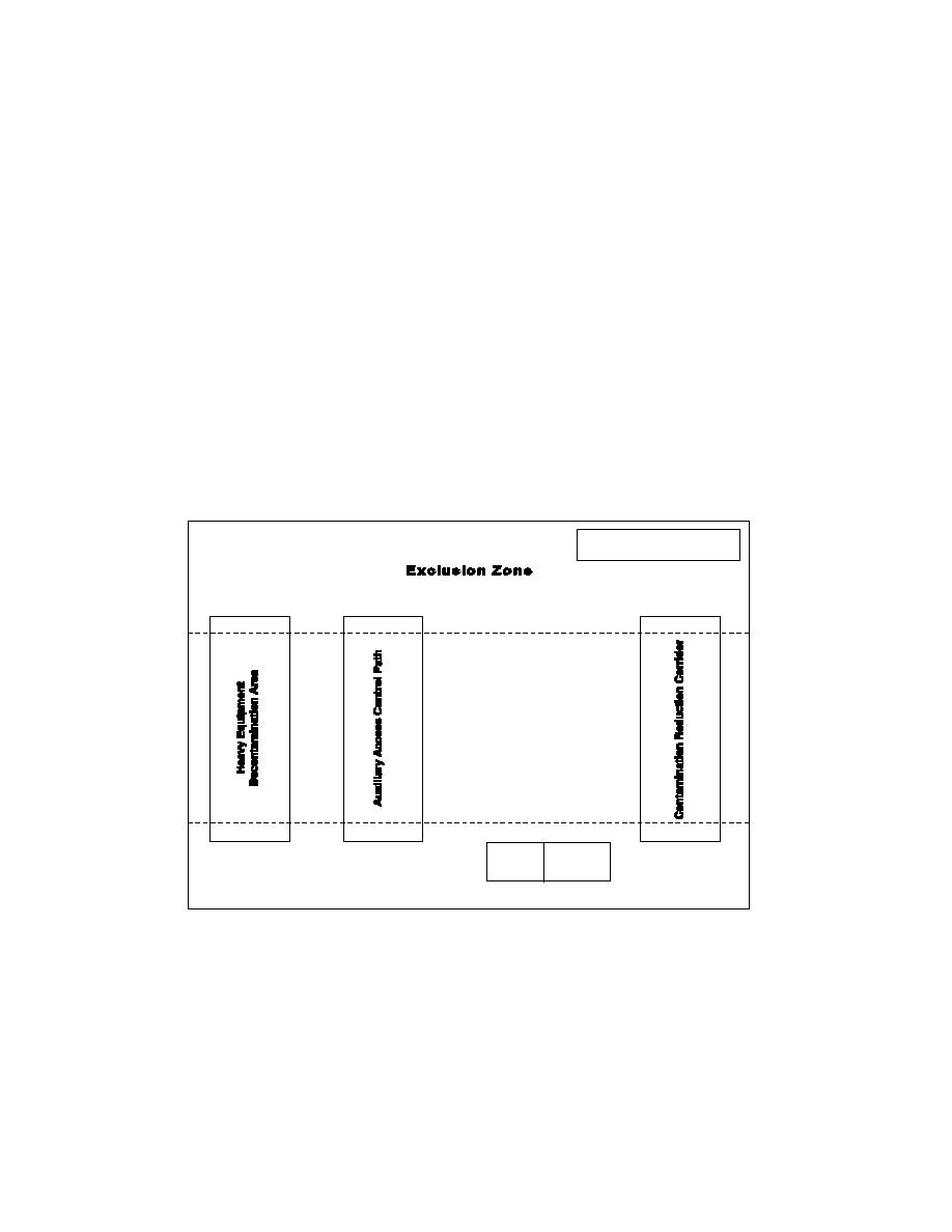
Figure 10-1 Example Layout of Contamination Reduction Corridors |
|
||
| ||||||||||
|
|  DOE-EM-STD-5503-94
clothing or equipment is contaminated with both radiological and hazardous material and this
process is used, mixed waste may be generated. Special precautions should be taken to ensure
this waste is properly handled, treated, stored and disposed.
10.3. LOCATION AND LAYOUT
An area within the Contamination Reduction Zone/Radiological Buffer Area is normally
designated the Contamination Reduction Corridor (CRC). The CRC controls access into and out
of the Exclusion Zone/Radiological Area and confines personnel decontamination activities to a
limited area. A separate CRC should be established for equipment. Figure 10-1 provides a
graphical depiction of an example layout of CRCs in relation to work zones.
FIGURE 10-1
Example Layout of Contamination Reduction Corridors
Professional judgment should be exercised in determining how the CRC should be organized and
what decontaminants should be used. Factors that should be considered include:
LEGEND
= Access Control Points
Hotline
Contamination
Reduction
Zone
_ _
Contamination Control Line
Redress
Dress
Support Zone
The extent and type of the expected hazard,
Meteorological conditions (wind direction),
Topography,
Levels of protection selected, and
Availability of equipment and supplies.
10-2
|
|
Privacy Statement - Press Release - Copyright Information. - Contact Us |
