 |
|||
|
|
|||
|
Page Title:
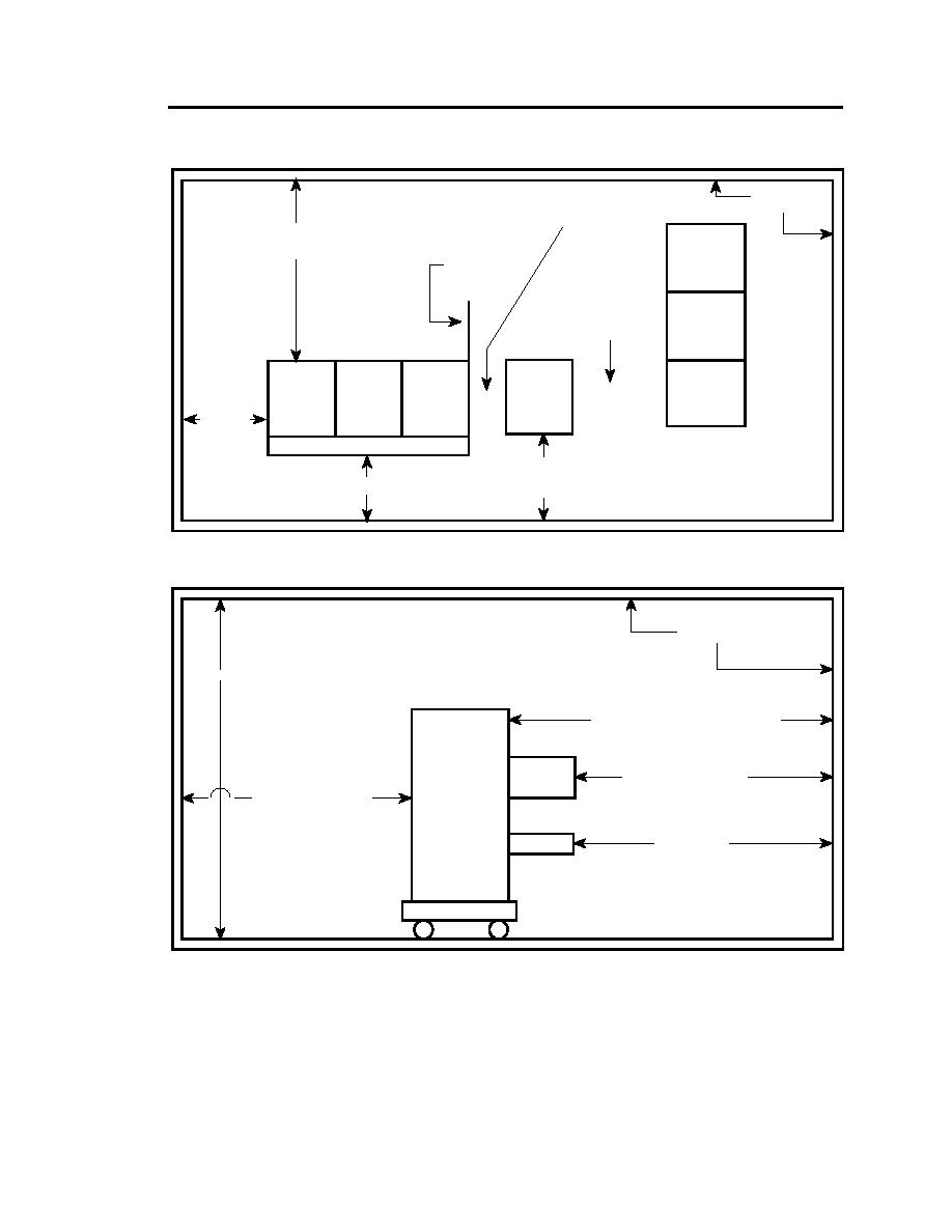
Fig. 9-4. Top View of Equipment Layout in a Room (Drawing is not to scale) |
|
||
| ||||||||||
|
|  DOE-HDBK-1092-98
Walls or other
No access required. No
obstructions
minimum space
requirement.
Distance as determined by Fig. 2-1
or 2-2 of Section 2, when power
Cabinet doors
is on, 24" when power is off.
must open at least
90 or the door
must be removed.
Access required -
with power off, 24";
with power on, refer
to Fig. 2-1 or 2-2 of
3 Bay
Section 2.
Equipment
Rack
3 Bay
Equipment
Equipment
Rack
Passageway
24" min.
Open Chassis
Distance as determined by Fig. 2-1 or 2-2 of Section 2.
If a chassis is open, measurement is made from the front
Operator Space
of the chassis to the wall or obstruction.
Fig. 9-4. Top View of Equipment Layout in a Room (Drawing is not to scale)
Ceiling, walls, or other
obstructions
Headroom - 6'6" minimum
Distance as determined by Fig. 2-1 or
2-2 of Section 2, when the chassis is closed.
Equipment
Rack
Distance as determined by
Open
Fig. 2-1 or 2-2 of Section 2.
Chassis
Distance as determined by
Fig. 2-1 or 2-2 of Section 2.
Operator Space
Writing Surface
Fig. 9-5. Side View of Equipment Layout in a Room (Drawing is not to scale)
9.10 CABLE/UTILITY MANAGEMENT SYSTEM
Cable supports and/or cable enclosures are installed for dedicated usage with enclosed electrical/
electronic equipment
9-15
|
|
Privacy Statement - Press Release - Copyright Information. - Contact Us |
