 |
|||
|
|
|||
|
Page Title:
Inductive Coupling Situation |
|
||
| ||||||||||
|
|  DOE-HDBK-1092-98
Power Cable
Tray
Pulse
Power
Supply
Load
ground
Multiconductor
Tray
I/O
Controller
ground
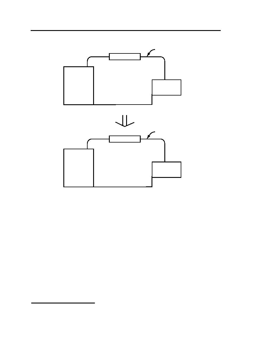
INDUCTIVE COUPLING SITUATION
Figure 10-6. The pulse power supply, its cable, load, and return form a transmitting loop which couples into
the loop formed by the controller, its multiconductor cabling, I/O and return. Note that in actual installations
these loops can be very large and very close.
(EMI) that may affect the cabinets. The cabinet ground remains separate from the dc signal ground
until it terminates at the master ground bus.
Eliminating grounds is not feasible for some instruments, such as thermocouples and some analyzers,
because they require a ground to obtain accurate measurements. Also, some instruments must be
grounded to ensure personnel safety.
When grounds cannot be eliminated, the solution to instrumentation ground loops lies in signal
isolators. These devices break the galvanic path (dc continuity) between all grounds while allowing
the analog signal to continue throughout the loop. An isolator also eliminates the noise of ac
continuity (common-mode voltage).2
2
Much of the information above came from the article which is titled "Causes and Cures of Instrumentation
Ground Loops," by Pat Power, Moore Industries, Houston, TX.
10-18
|
|
Privacy Statement - Press Release - Copyright Information. - Contact Us |
