 |
|||
|
|
|||
|
Page Title:
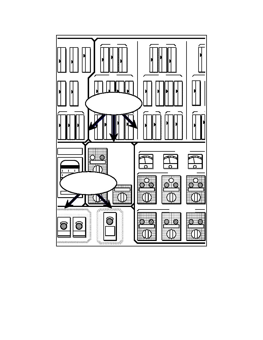
Figure B-1. Demarcation lines on a control panel |
|
||
| ||||||||||
|
|  DOE-STD-1044-93
1ST FLOOR
2ND FLOOR
CW TEMP IN
OUTSIDE
LP 1
LP 2
TEMP
FLOW
FLOW
100
100
100
100
100
100
100
100
100
10
75
75
75
75
75
75
75
75
75
7
50
50
50
50
50
50
50
50
50
5
25
25
25
25
25
25
25
25
25
2
0
0
0
0
0
0
0
0
0
CW TEMP OUT
TEMP
TEMP
AVG
EAST
SOUTH
WEST
AVG
EAST
SOUTH
WEST
LP 1
LP 2
AVG
100
100
100
100
100
100
100
100
100
100
100
75
75
75
75
75
75
75
75
75
75
75
50
50
50
50
50
50
50
50
50
50
50
Standard
25
25
25
25
25
25
25
25
25
25
25
Demarcation Lines
0
0
0
0
0
0
0
0
0
0
0
FAN P
HEAT
COOL
HEAT
COOL
HEAT
100
100
100
100
100
100
100
100
100
100
100
100
75
75
75
75
75
75
75
75
75
75
75
75
50
50
50
50
50
50
50
50
50
50
50
50
25
25
25
25
25
25
25
25
25
25
25
25
0
0
0
0
0
0
0
0
0
0
0
0
CIRCULATING PUMPS
MOTOR AMPS
FUEL USE
MASTER SW
CIRCULATING PMP START / STOP
Color-CodeAUXILIARY HEAT
d
Demarcation Lines
UNIT 1
UNIT 2
PMP 1
PMP 2
PMP 3
X100 CF / HR
OIL LIFT PMP START / STOP
ANNUNCIATOR
PMP 1
PMP 2
PMP 3
FUEL
SHUT
OFF
SILENCE
RESET
Figure B-1. Demarcation lines on a control panel.
B-6
|
|
Privacy Statement - Press Release - Copyright Information. - Contact Us |
