 |
|||
|
|
|||
|
Page Title:
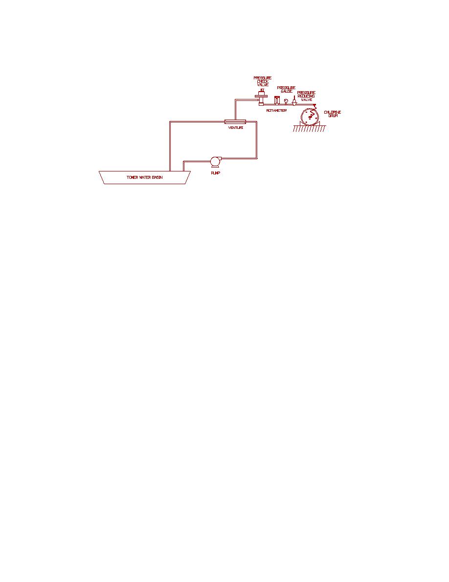
Figure 4.2. Cooling Water Chlorination System |
|
||
| ||||||||||
|
|  DOE-HDBK-1100-2004
Figure 4.2. Cooling Water Chlorination System
EXAMPLE PROCESS 2: COOLING WATER CHLORINATION SYSTEM. The cooling water chlorination system is designed to provide chlorination
to the basin of a cooling water system to prevent biological growth in the cooling water. Chlorine is provided from the vapor side of a 1-ton
cylinder. Pressure is reduced from the cylinder (normally 80 psig at 70ΕF) to 15 psig at the rotameter. The rotameter is adjusted manually to
provide an average flow rate of 2.5 to 3.0 pounds per hour to the pressure check valve. To operate properly, the chlorine gas supply must be
reduced to zero so that the vacuum from a venturi may draw a controlled amount of chlorine into the water stream. A pressure check valve
performs this function. Gas under pressure enters the pressure check valve. Its pressure is reduced to less than atmospheric as the gas passes
through two valves which do not open unless a vacuum is present on the downstream side. If the first valve passes gas when a vacuum is not
present, the second valve remains closed and contains the gas pressure in the unit. If the second valve also passes gas, the built-in pressure relief
valve permits this gas to pass out of the vent. A small pump recirculates water through the venturi creating the vacuum for the chlorine and
delivering chlorinated water to the basin. The pump's nominal flow rate is 30 gallons per hour.
25
|
|
Privacy Statement - Press Release - Copyright Information. - Contact Us |