 |
|||
|
|
|||
|
Page Title:
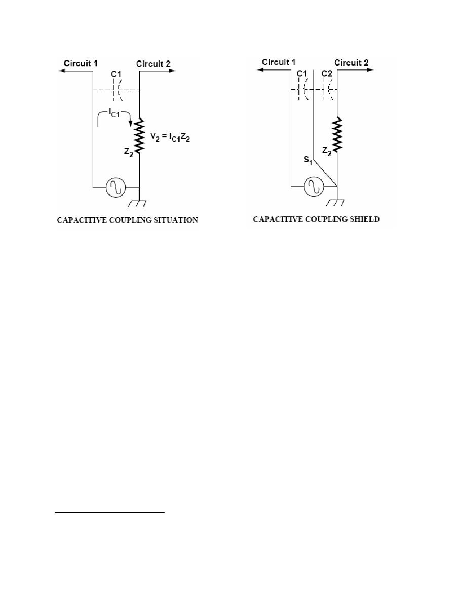
Capacitive Coupling Situation |
|
||
| ||||||||||
|
|  DOE-HDBK-1092-2004
Figure 10-4. Capacitance between
Figure 10-5. A shield has been
circuit 1 and circuit 2 is allowing
interposed between circuit 1 and circuit
current to be transferred into circuit
2. The coupling will be reduced as it
2 via an electric field. This current
shunts the coupled current around Z2
instead of through it. The interfering
circuit 2, and develops an
voltage could be increased instead of
interfering voltage.
decreased if not properly shunted.
3. Inductive Coupling. (Near-field, low-impedance loop-to-loop coupling) The technique for
increasing resistance to magnetic coupling in shielded cables is to ground both ends of the
shield to an effective signal return ground as is shown in Figures 10-6 and 10-7.
4. System Signal Returns. Each installation will require individual analysis and treatment. A
single ground poses no problem, but multiple grounds can result in a ground loop. These can
upset the proper functioning of instruments. A signal isolator offers a way of overcoming the
problem.
5. Instrumentation Grounding2. Equipment that is used to implement a control instrumentation
strategy (see Figure 10-8) makes use of a common signal ground as a reference for analog
signals. Any additional grounds that are introduced into the control circuit will almost
certainly cause ground loops to occur.
A typical process instrumentation loop is shown in Figure 10-8. It is a DC system that operates
at a specific voltage (24 volts in this case) to a master ground reference called a signal ground.
The instrumentation signal varies within the range of 4-20 mA, depending upon the value of the
variable (pressure, temperature, etc.) seen by the sensor. A precisely calibrated circuit takes
this mA signal and converts it into a form that can be used by a process-control computer, PLC,
2
The information in this section and figures 10-8 and 10-9 is reprinted with permission from the September
1991 issue of EC&M magazine 1991 Intertec Publishing Corporation. All rights reserved.
10-18
|
|
Privacy Statement - Press Release - Copyright Information. - Contact Us |
