 |
|||
|
|
|||
|
|
|||
| ||||||||||
|
|  DOE-HDBK-1092-2004
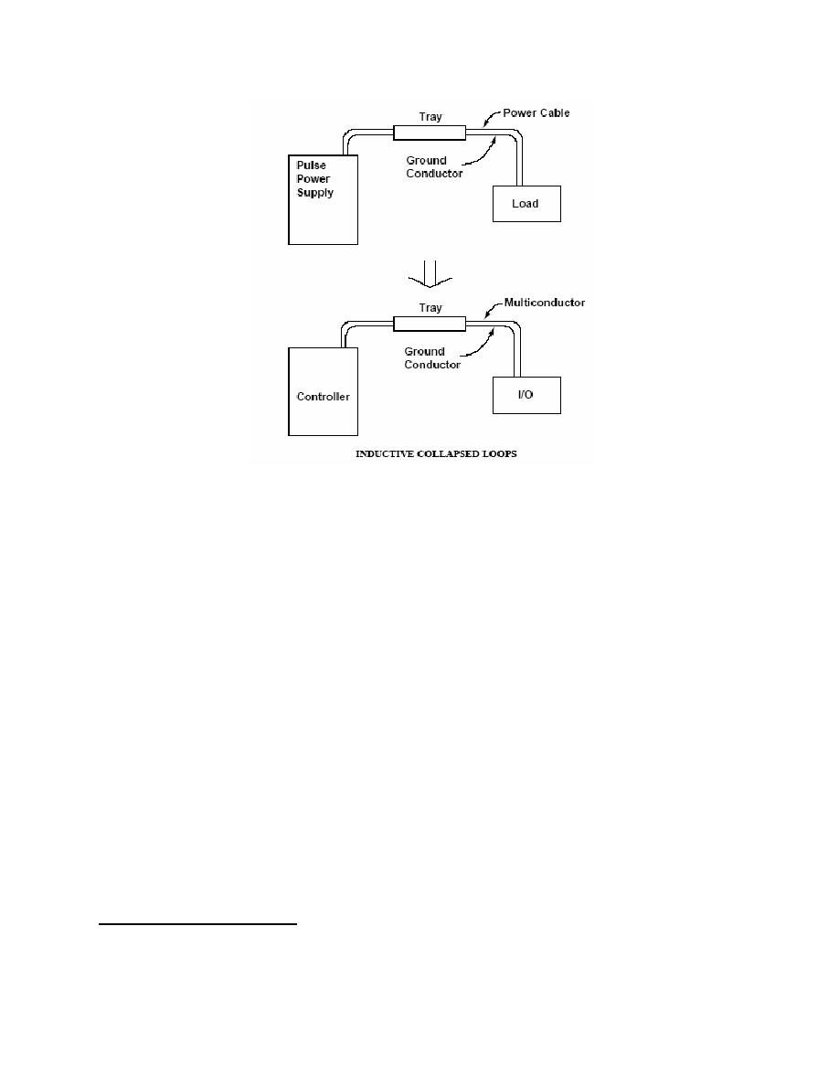
Figure 10-7. Intentional returns have been installed for both the pulse power supply and
the controller right in the trays for the cables. Both loops have been reduced to small
cross sections, reducing inductive coupling. Any electromagnetic (far field) radiation
being generated by the pulse power supply and its cabling will also be reduced.
Eliminating grounds is not feasible for some instruments, such as thermocouples and some
analyzers, because they require a ground to obtain accurate measurements. Also, some
instruments must be grounded to ensure personnel safety.
When grounds cannot be eliminated, the solution to instrumentation ground loops lies in signal
isolators. These devices break the galvanic path (dc continuity) between all grounds while
allowing the analog signal to continue throughout the loop. An isolator also eliminates the noise of
10.9.2.1.4 OPERATION AND MAINTENANCE
Before starting each operation (experiment, test, etc.) the exposed portions of the grounding
system should be visually checked for any damage and to determine that all necessary
connections have been made. If more than one operation is conducted every day, then visual
checks should be performed only at the beginning of each shift, if the grounding system will be
needed during that shift. The adequacy of the grounding system should be verified annually. It is
recommended that the grounding impedance within the equipment be maintained at 0.25 ohms or
less. (See IEEE 1100).
3
Much of the information above came from the article entitled Causes and Cures of Instrumentation Ground
Loops, by Pat Power, Moore Industries, Houston, TX.
10-20
|
|
Privacy Statement - Press Release - Copyright Information. - Contact Us |