 |
|||
|
Page Title:
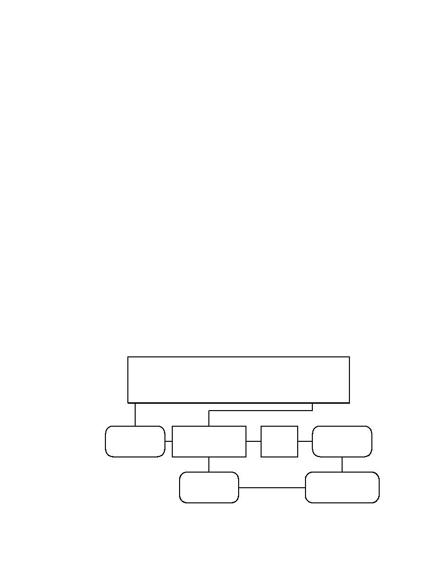
Figure 11. Typical tritium removal system flow schematic |
|
||
| ||||||||||
|
|  DOE-HDBK-1132-99
(3)
The cleanup system removes the tritium from the gas stream by breaking
down the hydrogen (i.e., H, D, and T) containing molecules on a hot,
precious metal catalyst.
(4)
The free H, D, and T atoms are recombined with oxygen in the catalytic
reactor to form water vapor.
(5)
The hot water vapor is cooled to a suitable temperature by passing the
gas stream through one or more heat exchangers.
(6)
The water is removed from the gas stream by passing the gas stream
through molecular sieve traps. A typical example of this type of cleanup
system is shown schematically in Figure 11.
Catalyst/molecular sieve tritium removal systems of this type can be very
effective. Depending on the tritiated species, the reduction in tritium
concentration for such systems has been measured at ratios of 10 6:1 to108:1
when operated in a once-through flow mode, in which the gas stream passes
from the glovebox, through the cleanup system, and out the stack to the
environment. In most situations, these types of cleanup systems are operated
in the continuous flow mode, where the gas stream is moved from the
glovebox, through the cleanup system, and back to the glovebox. When
Glovebox, Room, or Buidling
To Be Cleaned Up
Circulation
Gas To Gas
Gas
Catalysts
Blower
Heat Exchanger
Heater
Bed
Molecular
Water To Gas
Sieve Trap
Heat Exchanger
FIGURE 11. Typical tritium removal system flow schematic.
I-122
|
|
Privacy Statement - Press Release - Copyright Information. - Contact Us |
