 |
|||
|
|
|||
|
Page Title:
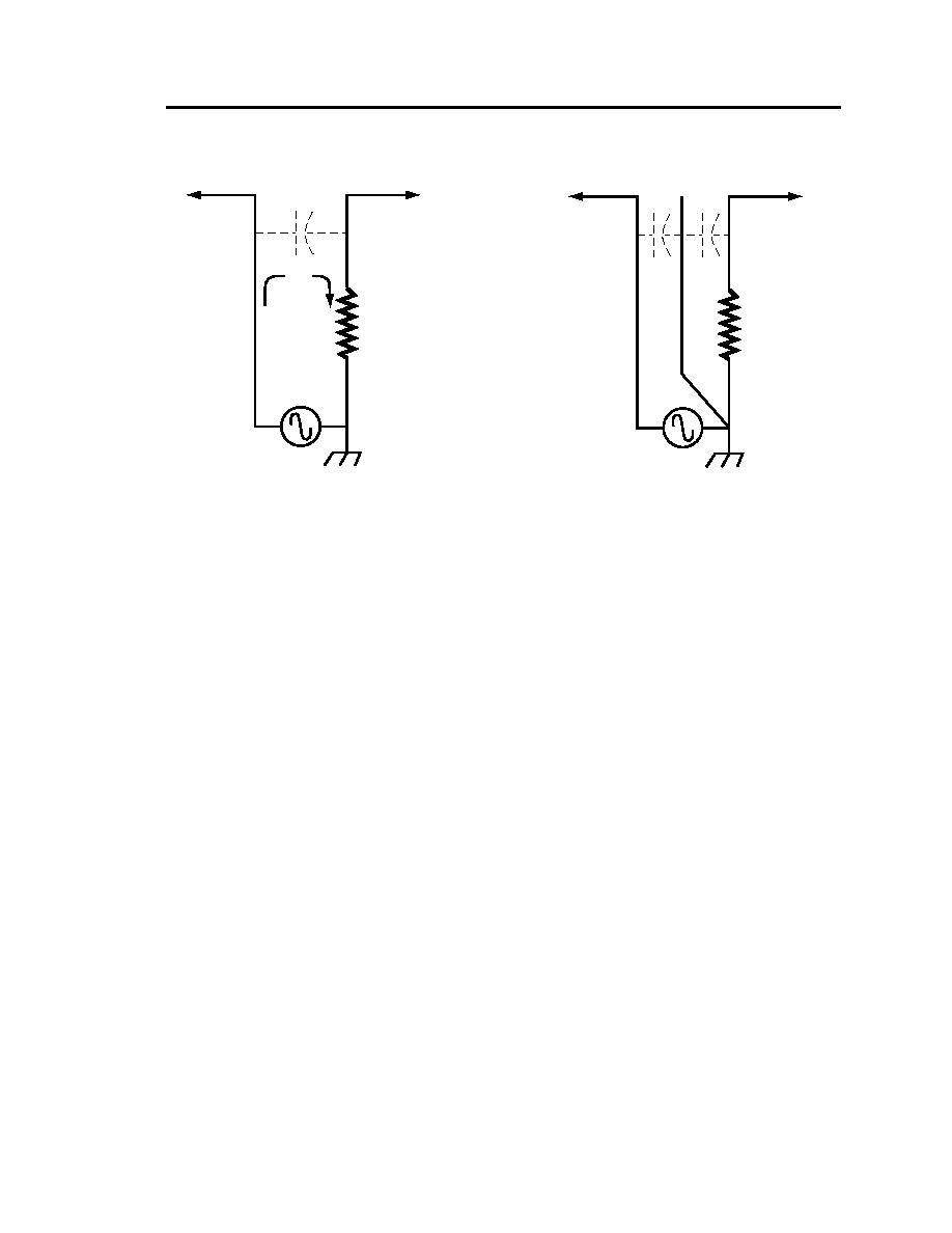
Capacitive Coupling Situation |
|
||
| ||||||||||
|
|  DOE-HDBK-1092-98
Circuit 1
Circuit 1
Circuit 2
Circuit 2
C1
C1
C2
IC1
V2 = IC1Z2
Z2
Z2
S1
CAPACITIVE COUPLING SITUATION
CAPACITIVE COUPLING SHIELD
Figure 10-5. A shield has been interposed between
circuit 2 is allowing current to be transferred into
circuit 1 and circuit 2. The coupling will be reduced
circuit 2 via an electric field. This current flows
as it shunts the coupled current around Z2 instead
of through it. The interfering voltage could be
an interfering voltage.
increased instead of decreased if not properly
shunted.
signals. Any additional grounds that are introduced into the control circuit will almost
certainly cause ground loops to occur.
A typical process instrumentation loop is shown in Figure 10-8. It is a DC system that operates at a
specific voltage (24 volts in this case) to a master ground reference called a signal ground. The
instrumentation signal varies within the range of 4-20 mA, depending upon the value of the variable
(pressure, temperature, etc.) seen by the sensor. A precisely calibrated circuit takes this mA signal
and converts it into a form that can be used by a process-control computer, PLC, dedicated
instrument, or whatever controller that supervises the system. In this example, the mA signal is
converted to a 1-5 V signal for a chart recorder. At 4 mA, the voltage measured by the recorder is
250 x .004 = 1 V. At 20 mA, the measured voltage is 5 V. Normally, the recorder scale is calibrated
so the voltage reads directly in 0F, psi, etc.
In order to minimize the danger of introducing ground loops into this complicated network of
sensitive equipment, a dedicated instrumentation system ground bus is usually employed. This bus
ultimately receives grounds from the signal common, the dc power supply common, the cabinet
ground, and the instrumentation ac power ground. The bus is tied to earth via the building ground
and the plant ground grid. Figure 10-9 shows the typical way in which interconnection of these
various grounds is accomplished.
The cabinet ground is a safety ground that protects equipment and personnel from accidental shock
hazards while providing a direct drain line for any static charges or electromagnetic interference
10-17
|
|
Privacy Statement - Press Release - Copyright Information. - Contact Us |
