 |
|||
|
|
|||
|
|
|||
| ||||||||||
|
|  DOE-HDBK-1092-98
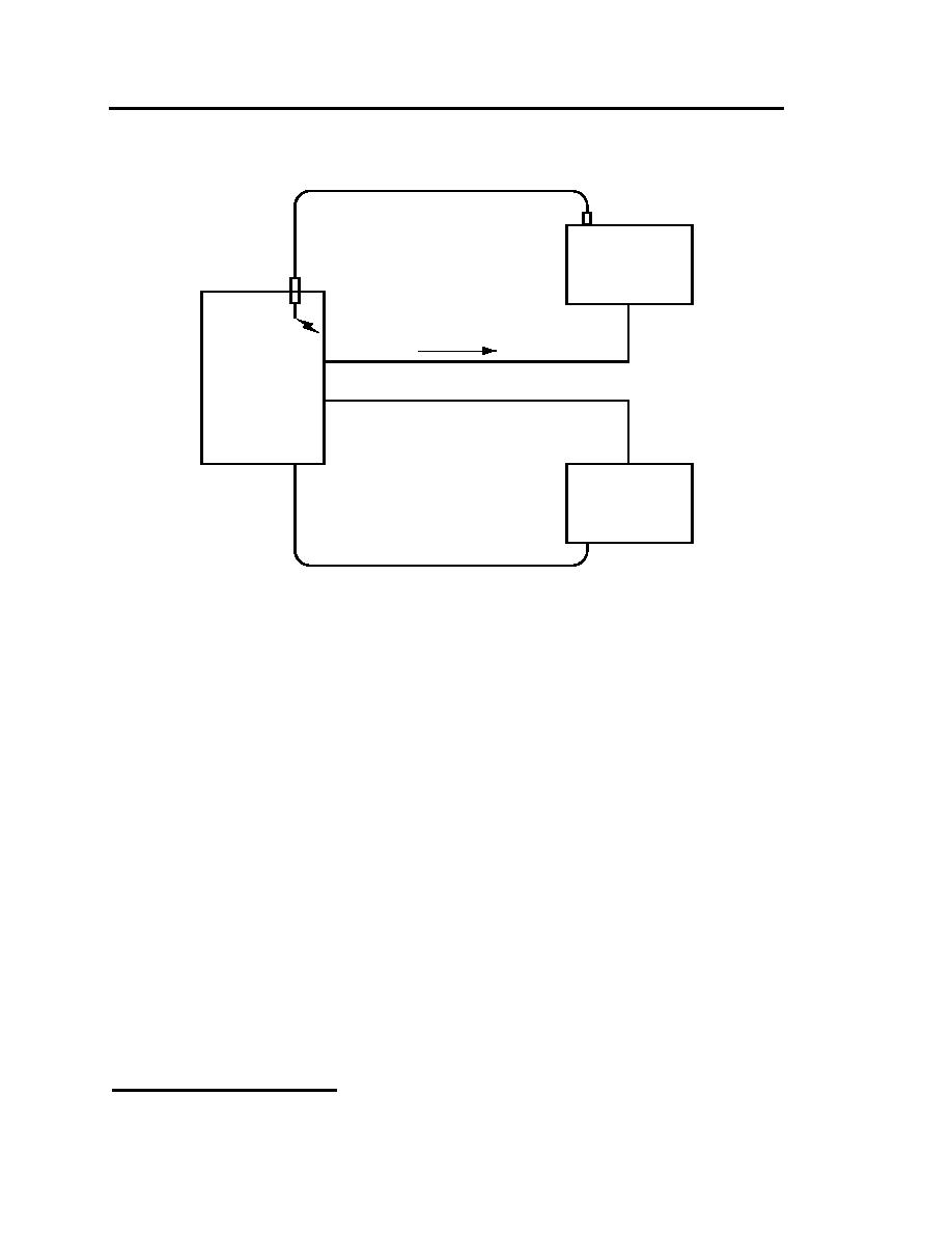
Process Power Cable
Process
Power
Supply
arc
I arc
Process Power Ground
Process Control Ground
Process
Enclosure
Process
Control
Control/Instrument Lines
CONDUCTIVE COUPLING SOLUTION
Figure 10-3. It has been possible to install a separate return conductor for the power supply. The arc currents
no longer appear in series with the process controls. There is no conductive coupling.
2. Capacitive Coupling. (High-impedance proximity coupling) The technique for increasing
resistance to capacitive coupling among cables is to ground one end of the shield to produce
the shortest, most direct shunt path back to the source of the coupled current as is shown in
Figures 10-4 and 10-5.
Caution: It is possible to inadvertently INCREASE coupling between source and load if the
shield ground does not properly shunt the current coupled onto the shield.
3. Inductive Coupling. (Near-field, low-impedance loop-to-loop coupling) The technique for
increasing resistance to magnetic coupling in shielded cables is to ground BOTH ends of the
shield to an effective signal return ground as is shown in Figures 10-6 and 10-7.
4. System Signal Returns. Each installation will require individual analysis and treatment. A
single ground poses no problem, but multiple grounds can result in a ground loop. These can
upset the proper functioning of instruments. A signal isolator offers a way of overcoming the
problem.
strategy (see Figure 10-8) makes use of a common signal ground as a reference for analog
1
The information in this section and figures 10-8 and 10-9 are reprinted with permission from the September
1991 issue of EC&M magazine copyright (c) 1991 Intertec Publishing Corporation. All rights reserved.
10-16
|
|
Privacy Statement - Press Release - Copyright Information. - Contact Us |
