 |
|||
|
|
|||
|
|
|||
| ||||||||||
|
|  DOE-HDBK-1092-2004
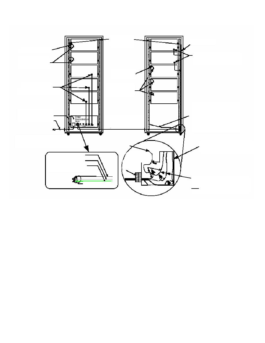
RACK #1
RACK #2
Cabinet rails
used for
AC power strip.
bonding.
Bonding Conductor
These chassis shall be
bonded/grounded internally
Identified equipment
from the ground wire in cord.
ground points.
Bonding
Conductor
These chassis shall be
Identified
bonded/grounded
equipment ground
internally from the ground
points.
wire in cord.
Required ground or bonding
Required
wire common to the ground
bonding/grounding
wire of the power strip and the
(Same gauge or
ground wire of the ac power
"Rack #1" supplying
larger than ac power
cable coming into this second
single phase, ac power
cable.)
rack (Same gauge or larger
to "Rack #2).
than the ac power cable.)
NOTE: This drawing represents a typical
Typical configuration for
120/208 Volt, three phase Wye, 5
Metallic case of typical power strip is
bonding/grounding wire
wire, ac power for Rack #1.
bonded to the grounding conductor
going to cabinet rail
through means of mounting screw.
Energized conductor - Black
(Hot, AC source)
Grounded conductor - White
Compression
(Neutral, AC return)
fitting (not
Grommet
Green
Equipment grounding conductor
"NM" type)
Green, Green with Yellow stripe,
Bare (Ground)
The Equipment Grounding Conductor
Black
and the Grounded Conductor shall
White
Typical Single-Phase, AC plug
for power to Rack #2
NOT be connected together at power
Incoming ac power
(Typically, 120 V,
cable termination.
Single Phase)
Figure 9-2
1) Have a common grounding or bonding bus (normally a cabinet rail).
2) When the enclosure contains more than one bay, bond all grounding or bonding busses
together.
3) All mounted chassis within rack cabinets shall have a grounding or bonding conductor
attached to the common grounding or bonding bus when the chassis is not grounded or
bonded through the power cord.
4) The grounding or bonding conductor shall be permanent and continuous.
5) Subassemblies mounted in other types of enclosures should be bonded by adequate
preparation of the mounting surfaces or by the use of a bonding conductor.
6) To provide protection against grounding or bonding conductor breakage, conductors
between the common grounding or bonding bus and moveable chassis should be braided
cable or stranded wire.
9-4
|
|
Privacy Statement - Press Release - Copyright Information. - Contact Us |
